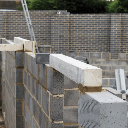


Underground drainage is one of the core elements of any UK building project. Whether you are installing a new foul line on an extension, upgrading old pipework or adding new rainwater connections, getting the below-ground system right prevents blockages, backups and costly digging later on. This guide walks through the essentials in a practical, no-nonsense way that works for both experienced groundworkers and confident DIYers.
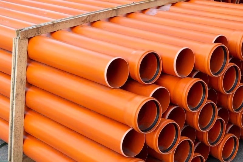
For fittings and pipework, you can view our complete range of underground drainage products: Underground Drainage Range
How UK Underground Drainage Systems Work
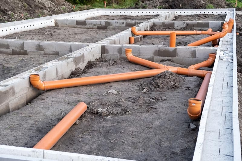
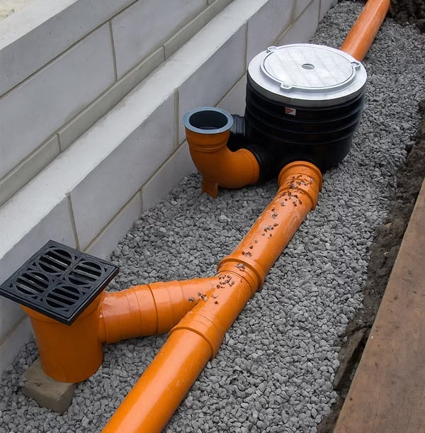
Most UK drainage works on gravity. Foul water and rainwater move through the system using carefully set gradients, smooth directional changes and reliable seals. Good layout and component choice ensure the system stays free flowing, easy to maintain and compliant with Building Regulations.
A typical setup includes:
- 110mm PVC-U pipe for foul and surface water
- Bends, junctions and adaptors
- Bottle gullies and hoppers for waste and rainwater
- Rodding points and access chambers
- Suitable bedding and backfill
Pipe Sizes and Materials
Standard UK Pipe Sizes
Most domestic underground drainage uses 110mm pipe, which is the standard size for foul drainage, soil stacks and waste connections. Larger systems, including commercial jobs, can step up to 160mm and beyond.
Example product: 3m Single Socket Pipe 110mm
Pipe Materials
Modern systems use PVC-U, chosen for durability, smooth internal bore and ease of installation. Older properties may still have clay pipe, and you can convert between the two using suitable adaptors:
Correct Pipe Fall Gradients
Setting the correct fall is essential. Too shallow and the system slows down. Too steep and liquids outrun solids.
| Pipe Diameter | Minimum Gradient | Common Trade Gradient | Notes |
|---|---|---|---|
| 110mm pipe | 1 in 40 | 1 in 60 to 1 in 40 | Domestic foul and waste drainage |
| 160mm pipe | 1 in 60 | 1 in 100 to 1 in 60 | Higher flow systems |
For official guidance, see Building Regulations Part H: Approved Document H
How to Calculate Falls and Gradients
The fall of a drainage pipe is the vertical drop over the horizontal length of the run. Underground drainage relies on gravity, so calculating the correct fall ensures liquids and solids travel at the right speed to avoid silting or blockages.
Falls are normally expressed as a ratio, such as 1 in 40. This means that for every 40 units of horizontal pipe, the pipe drops by 1 unit vertically. The measurement unit does not matter; the ratio behaves the same in metres, centimetres or millimetres.
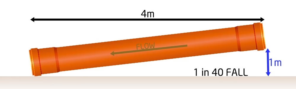
Example: Understanding a 1 in 40 Fall
- A run of 40m would drop 1m
- A run of 4m would drop 0.1m (100mm)
- A run of 2m would drop 0.05m (50mm)
If the pipe run increases or decreases, the drop scales proportionally.
Calculating Gradient from Fall
Sometimes it is useful to convert a fall (ratio) into a gradient (number). The gradient is calculated by dividing the vertical fall by the horizontal distance:
Gradient = Fall ÷ Distance
Using the 1 in 40 example:
Gradient = 1 ÷ 40 = 0.025
This gives a gradient of 0.025, which is another way to express the same fall.
Worked Example: Calculating Gradient
If a 24 metre pipe run drops 0.30 metres:
- Gradient = 0.30 ÷ 24
- Gradient = 0.0125
To convert this back into a ratio (fall):
Fall ratio = 1 ÷ 0.0125 = 80
This gives a fall of 1 in 80.
Calculating Fall When Gradient Is Known
If you know the gradient as a decimal, you can calculate the required drop over any distance using:
Fall = Gradient × Distance
Worked Example: Calculate fall over 50m with a gradient of 1 in 80
- Convert 1 in 80 to a number: 1 ÷ 80 = 0.0125
- Fall = 0.0125 × 50
- Fall = 0.625m (625mm)
These calculations are important when setting out drainage runs between chambers, around obstacles or when coordinating invert levels on sloping ground.
Minimum Depths for Underground Drainage
| Location | Minimum Cover Depth | Notes |
|---|---|---|
| Garden or soft ground | 450mm | Most common installations |
| Driveway or traffic area | 600mm | Often requires stronger backfill |
| Deeper excavations | 900mm+ | May require additional mechanical protection |
Pipe Depths and Proximity to Foundations
Building Regulations Part H also specifies how close drainage can be to foundations:
- Pipes must be at least 150mm below the underside of foundations, or
- At least 1m horizontally from the foundation edge
This prevents ground movement affecting the pipework and avoids undermining structural loads.
Common Fittings and When to Use Them
Bends
These allow changes of direction while maintaining smooth flow. Shallow bends are preferable to sharp direction changes.
- 15 degree single socket bend
- 15 degree double socket bend
- 30 degree single socket bend
- 30 degree double socket bend
- 45 degree single socket bend
- 45 degree double socket bend
- 90 degree single socket bend
- 90 degree double socket bend
- 90 degree rest bend
[image: various underground drainage bends arranged on ground]
Regulatory Limits on Direction Changes
To maintain acceptable flow conditions and ensure rodding access:
- No more than 22.5 degrees change of direction without access
- No more than 135 degrees total change of direction between access points
- A 90 degree bend must always have a rodding point immediately upstream
Junctions
Bottle Gullies, Traps and Hoppers
Bottle gullies connect wastewater and rainwater into the underground drainage system. They trap debris, stop odours and provide a clean access point. They are designed for greywater and surface water only and must not be used on foul soil drainage from WCs or soil stacks.
- Standard bottle gully
- Back inlet bottle gully
- Bottle gully raiser
- Bottle gully grid only
- Square to round adaptor
[image: diagram showing bottle gully connected to drainage run]
Hoppers
Adaptors and Connectors
- Universal waste adaptor
- Rainwater spigot adaptor
- Plastic to plastic adaptor
- Rainwater adaptor
- Coupler
- Slip coupler
- Socket plug
- External socket plug
Rodding and Access Points
Access points keep the system maintainable and save unnecessary digging.
[image: engineer rodding through a rodding eye]
Access Spacing Requirements
- Access points should be no more than 22m apart in domestic systems
- Where direction changes occur, a rodding point or chamber must be installed
- A rodding point is required at the base of every soil stack unless immediate chamber access is available
Soil Drainage vs Waste Drainage
Soil Drainage (Foul Water)
- From WCs and soil stacks
- Always uses 110mm pipe
- Must connect directly into the foul run or an inspection chamber
- No bottle gullies on these lines
Waste Drainage (Greywater and Surface Water)
- From basins, baths, showers, sinks and appliances
- Rainwater downpipes where permitted
- Can enter through bottle gullies or hoppers
- Traps stop smells and catch debris
[image: diagram showing soil stack connection vs waste via bottle gully]
Installation Tips for Reliable Underground Drainage
1. Proper Bedding
The recommended method under BS EN 1610 includes:
- 100mm pea shingle bedding beneath the pipe
- 100mm granular surround above the crown of the pipe
- Granular backfill meeting Class 8 or Class 10 specifications
- No stones larger than 40mm within 150mm of the pipe
- Layered compaction to prevent settlement issues
2. Lubricate Fittings
Helps seals seat correctly and reduces displacement. Pipe Lubricant 500ml
3. Avoid Sharp Direction Changes
4. Check Levels Frequently
5. Protect Areas Under Driveways
Note on Invert Levels and Setting Out
Setting accurate invert levels is essential for maintaining proper falls and ensuring chambers connect correctly. This process involves working to reference benchmarks and adjusting pipe heights to avoid clashes with foundations or existing services. A detailed treatment of invert level setting, including tolerance limits and advanced layout considerations, will be covered in a separate dedicated guide.
Common Layout Example
A typical domestic system might include:
- A soil stack dropping into a 110mm rest bend
- A main run leading to the first chamber
- Junctions picking up kitchen or utility waste
- Bottle gullies serving rainwater and external appliances
- Rodding points at direction changes
- Outfall into an inspection chamber connecting to the sewer
[image: example layout for house extension drainage]
Technical Note: Flow Velocity and Self Cleansing Requirements
To prevent silting and maintain long-term system performance, drains must achieve a minimum self-cleansing velocity. Under UK practice and BS EN 752 guidance:
- Minimum self-cleansing velocity: 0.7 m/s under normal flow
- Maximum recommended velocity: 3.0 m/s to prevent pipe erosion
- 110mm PVC-U pipes typically meet these conditions when laid between 1 in 40 and 1 in 60 gradients
This is why gradients outside recommended limits can lead to either silting (too flat) or solids being left behind (too steep). Maintaining proper fall is essential to system reliability.
Final Thoughts
Underground drainage is straightforward when you understand the basics: correct falls, suitable fittings and sensible access points. Add in awareness of the key regulatory requirements and your system will run for decades with minimal maintenance.
Browse our full range of underground pipes and fittings here: Shop Underground Drainage
Further Reading
- Approved Document H – Drainage and Waste Disposal (UK Building Regulations)
- BS EN 752 – Drain and Sewer Systems Outside Buildings (Performance Requirements)
- BS EN 1610 – Construction and Testing of Drains and Sewers
- Water UK – Developer Services and Sewer Adoption Guidance
- CIRIA SuDS Manual – Sustainable Drainage Systems Guidance
- Thames Water – Drainage, Sewers and Building Over Drains Guidance
- Scottish Water – Drainage and Sewer Technical Resources
- NI Water – Sewerage Design Guide (Northern Ireland)